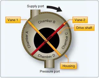
Figure 8. Schematic of vane-type air pump
Medium Pressure Pneumatic Systems
A medium-pressure pneumatic system (50–150 psi) usually does not include an air bottle. Instead, it generally draws air from the compressor section of a turbine engine. This process is often called bleed air and is used to provide pneumatic power for engine starts, engine deicing, wing deicing, and in some cases, it provides hydraulic power to the aircraft systems (if the hydraulic system is equipped with an air-driven hydraulic pump). Engine bleed air is also used to pressurize the reservoirs of the hydraulic system. Bleed air systems are discussed in more detail in the powerplant section.
Low Pressure Pneumatic Systems
Many aircraft equipped with reciprocating engines obtain a supply of low-pressure air from vane-type pumps. These pumps are driven by electric motors or by the aircraft engine. Figure 8 shows a schematic view of one of these pumps, which consists of a housing with two ports, a drive shaft, and two vanes. The drive shaft and the vanes contain slots so the vanes can slide back and forth through the drive shaft. The shaft is eccentrically mounted in the housing, causing the vanes to form four different sizes of chambers (A, B, C, and D). In the position shown, B is the largest chamber and is connected to the supply port. As depicted in Figure 8, outside air can enter chamber B of the pump. When the pump begins to operate, the drive shaft rotates and changes positions of the vanes and sizes of the chambers. Vane No. 1 then moves to the right, separating chamber B from the supply port. Chamber B now contains trapped air.
|
Figure 8. Schematic of vane-type air pump |
As the shaft continues to turn, chamber B moves downward and becomes increasingly smaller, gradually compressing its air. Near the bottom of the pump, chamber B connects to the pressure port and sends compressed air into the pressure line. Then chamber B moves upward again becoming increasingly larger in area. At the supply port, it receives another supply of air. There are four such chambers in this pump and each goes through this same cycle of operation. Thus, the pump delivers to the pneumatic system a continuous supply of compressed air from 1 to 10 psi. Low-pressure systems are used for wing deicing boot systems.
Pneumatic Power System Maintenance
Maintenance of the pneumatic power system consists of servicing, troubleshooting, removal, and installation of components, and operational testing.
The air compressor’s lubricating oil level should be checked daily in accordance with the applicable manufacturer’s instructions. The oil level is indicated by means of a sight gauge or dipstick. When refilling the compressor oil tank, the oil (type specified in the applicable instructions manual) is added until the specified level. After the oil is added, ensure that the filler plug is torqued and safety wire is properly installed.
The pneumatic system should be purged periodically to remove the contamination, moisture, or oil from the components and lines. Purging the system is accomplished by pressurizing it and removing the plumbing from various components throughout the system. Removal of the pressurized lines causes a high rate of airflow through the system, causing foreign matter to be exhausted from the system. If an excessive amount of foreign matter, particularly oil, is exhausted from any one system, the lines and components should be removed and cleaned or replaced.
Upon completion of pneumatic system purging and after reconnecting all the system components, the system air bottles should be drained to exhaust any moisture or impurities that may have accumulated there.