Figure 3. Pneumatic control valve
Pneumatic System Components
Pneumatic systems are often compared to hydraulic systems, but such comparisons can only hold true in general terms. Pneumatic systems do not utilize reservoirs, hand pumps, accumulators, regulators, or engine-driven or electrically driven power pumps for building normal pressure. But similarities do exist in some components.
Air Compressors
On some aircraft, permanently installed air compressors have been added to recharge air bottles whenever pressure is used for operating a unit. Several types of compressors are used for this purpose. Some have two stages of compression, while others have three, depending on the maximum desired operating pressure.
Relief Valves
Relief valves are used in pneumatic systems to prevent damage. They act as pressure limiting units and prevent excessive pressures from bursting lines and blowing out seals.
Control Valves
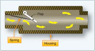
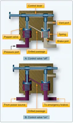
Control valves are also a necessary part of a typical pneumatic system. Figure 3 illustrates how a valve is used to control emergency air brakes. The control valve consists of a three-port housing, two poppet valves, and a control lever with two lobes.
|
Figure 3. Pneumatic control valve |
In Figure 3A, the control valve is shown in the off position. A spring holds the left poppet closed so that compressed air entering the pressure port cannot flow to the brakes. In Figure 3B, the control valve has been placed in the on position. One lobe of the lever holds the left poppet open, and a spring closes the right poppet. Compressed air now flows around the opened left poppet, through a drilled passage, and into a chamber below the right poppet. Since the right poppet is closed, the high-pressure air flows out of the brake port and into the brake line to apply the brakes.
To release the brakes, the control valve is returned to the off position. [Figure 3A] The left poppet now closes, stopping the flow of high-pressure air to the brakes. At the same time, the right poppet is opened, allowing compressed air in the brake line to exhaust through the vent port and into the atmosphere.
Check Valves
Check valves are used in both hydraulic and pneumatic systems. Figure 4 illustrates a flap-type pneumatic check valve. Air enters the left port of the check valve, compresses a light spring, forcing the check valve open and allowing air to flow out the right port. But if air enters from the right, air pressure closes the valve, preventing a flow of air out the left port. Thus, a pneumatic check valve is a one-direction flow control valve.
|
Figure 4. Flap-type pneumatic check valve |
Restrictors
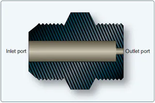
Restrictors are a type of control valve used in pneumatic systems. Figure 5 illustrates an orifice-type restrictor with a large inlet port and a small outlet port. The small outlet port reduces the rate of airflow and the speed of operation of an actuating unit.
|
Figure 5. Variable pneumatic restrictor |
Variable Restrictor
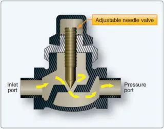
Another type of speed-regulating unit is the variable restrictor. [Figure 6] It contains an adjustable needle valve, which has threads around the top and a point on the lower end. Depending on the direction turned, the needle valve moves the sharp point either into or out of a small opening to decrease or increase the size of the opening. Since air entering the inlet port must pass through this opening before reaching the outlet port, this adjustment also determines the rate of airflow through the restrictor.
|
Figure 6. Pneumatic orifice valve |
Filters
Pneumatic systems are protected against dirt by means of various types of filters. A micronic filter consists of a housing with two ports, a replaceable cartridge, and a relief valve. Normally, air enters the inlet, circulates around the cellulose cartridge, and flows to the center of the cartridge and out the outlet port. If the cartridge becomes clogged with dirt, pressure forces the relief valve open and allows unfiltered air to flow out the outlet port.
A screen-type filter is similar to the micron filter but contains a permanent wire screen instead of a replaceable cartridge. In the screen filter, a handle extends through the top of the housing and can be used to clean the screen by rotating it against metal scrapers.
Desiccant/Moisture Separator
The moisture separator in a pneumatic system is always located downstream of the compressor. Its purpose is to remove any moisture caused by the compressor. A complete moisture separator consists of a reservoir, a pressure switch, a dump valve, and a check valve. It may also include a regulator and a relief valve.
The dump valve is energized and deenergized by the pressure switch. When deenergized, it completely purges the separator reservoir and lines up to the compressor. The check valve protects the system against pressure loss during the dumping cycle and prevents reverse flow through the separator.
Chemical Drier
Chemical driers are incorporated at various locations in a pneumatic system. Their purpose is to absorb any moisture that may collect in the lines and other parts of the system. Each drier contains a cartridge that should be blue in color. If otherwise noted, the cartridge is to be considered contaminated with moisture and should be replaced.
Emergency Backup Systems
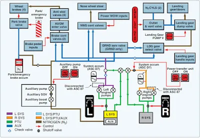
Many aircraft use a high-pressure pneumatic back-up source of power to extend the landing gear or actuate the brakes, if the main hydraulic braking system fails. The nitrogen is not directly used to actuate the landing gear actuators or brake units but, instead, it applies the pressurized nitrogen to move hydraulic fluid to the actuator. This process is called pneudraulics. The following paragraph discusses the components and operation of an emergency pneumatic landing gear extension system used on a business jet. [Figure 7]
|
Figure 7. Pneumatic emergency landing gear extension system |
Nitrogen Bottles
Nitrogen used for emergency landing gear extension is stored in two bottles, one bottle located on each side of the nose wheel well. Nitrogen from the bottles is released by actuation of an outlet valve. Once depleted, the bottles must be recharged by maintenance personnel. Fully serviced pressure is approximately 3,100 psi at 70 °F/21 °C, enough for only one extension of the landing gear.
Gear Emergency Extension Cable and Handle
The outlet valve is connected to a cable and handle assembly. The handle is located on the side of the copilot’s console and is labeled EMER LDG GEAR. Pulling the handle fully upward opens the outlet valve, releasing compressed nitrogen into the landing gear extension system. Pushing the handle fully downward closes the outlet valve and allows any nitrogen present in the emergency landing gear extension system to be vented overboard. The venting process takes approximately 30 seconds.
Dump Valve
As compressed nitrogen is released to the landing gear selector/dump valve during emergency extension, the pneudraulic pressure actuates the dump valve portion of the landing gear selector/dump valve to isolate the landing gear system from the remainder of hydraulic system. When activated, a blue DUMP legend is illuminated on the LDG GR DUMP V switch, located on the cockpit overhead panel. A dump valve reset switch is used to reset the dump valve after the system has been used and serviced.
Emergency Extension Sequence:
1. Landing gear handle is placed in the DOWN position.
2. Red light in the lnding gear control handle is illuminated.
3. EMER LDG GEAR handle is pulled fully outward.
4. Compressed nitrogen is released to the landing gear selector/dump valve.
5. Pneudraulic pressure actuates the dump valve portion of the landing gear selector/dump valve.
6. Blue DUMP legend is illuminated on the LDG GR DUMP switch.
7. Landing gear system is isolated from the remainder of hydraulic system.
8. Pneudraulic pressure is routed to the OPEN side of the landing gear door actuators, the UNLOCK side of the landing gear uplock actuators, and the EXTEND side of the main landing gear sidebrace actuators and nose landing gear extend/retract actuator.
9. Landing gear doors open.
10. Uplock actuators unlock.
11. Landing gear extends down and locks.
12. Three green DOWN AND LOCKED lights on the landing gear control panel are illuminated.
13. Landing gear doors remain open.