AUTOMATIC FLIGHT CONTROL SYSTEM(MODES OF OPERATION)
AUTOMATIC FLIGHT CONTROL SYSTEM (AFCS)
The Auto Flight Control Augmentation System (AFCAS) is a combination of three sub systems. These systems are on Automatic Flight Control System (AFCS), a Flight Augmentation System (FAS) and a Thrust Management System (TMS). A Maintenance Control Computer (MCC) and a Remote Maintenance Panel (RMP) are also part of the system. The MCC and RMP make one-man maintenance of the system possible.
The automatic flight control system has the following functions:
• Autopilot
• Flight Director
• Altitude Alerting
The AFCS is a system with three identical Flight Control Computers (FCC) and dual- aileron, rudder and elevator servo’s. In the critical flight modes, autoland, go-around and take-off, the system has maximum redundancy. In these modes the system uses all three flight control computers and the maximum available sensors. In all other modes the AFCS uses a single flight control computer and a single set of servo’s.
The autopilot/flight director gives steering signals to fly the aircraft as selected by the crew. The autopilot steers the aircraft directly with servo’s, the flight director gives only visual steering commands, how to control the aircraft, to the crew.
AUTOPILOT
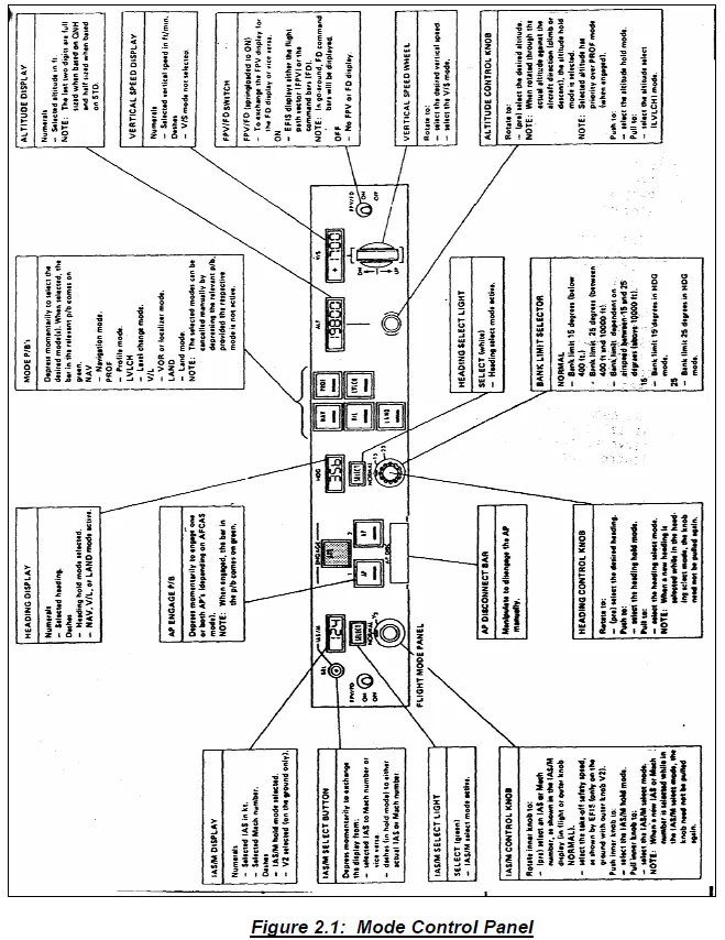
The automatic flight control system has vertical, horizontal, combined vertical and horizontal, and flight director/flight path vector functions. On a Flight Mode Panel (FMP) as shown in Figure 2.1, the crew selects the functions or modes.
The Electronic Flight Instrument System (EFIS) shows selected and active modes.

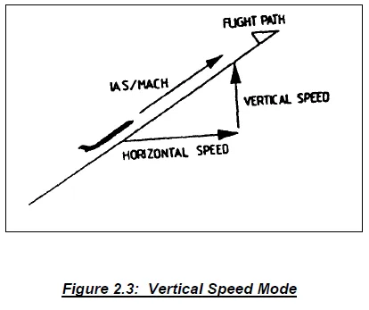
VERTICAL SPEED MODE
In the vertical speed mode the AFCS makes steering signals to fly the aircraft with a vertical speed set by the crew. The crew sets the vertical speed on the flight mode panel which also has a display to show the selected vertical speed.
ALTITUDE HOLD MODE
In the altitude hold mode the AFCS makes steering signals to level the aircraft off, and then holds the altitude at which the aircraft flies.
Figure 2.4 shows the autopilot in attitude hold mode. The mode of the flight director is not indicated since it could be in any selected mode. The servo motor has been clamped by the switch above it, grounding out its fixed field voltage. This also clamps the position of the synchro rotor.
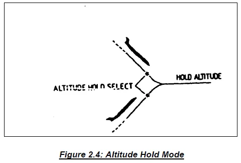
Subsequently, whenever the pitch attitude error signal does not correspond to the airplane pitch attitude command by the position of the control synchro rotor, there is a difference signal into the transfer valve amplifier. This signal operates the elevators to restore the pitch attitude the airplane had when the autopilot went into the attitude hold mode. Other signals are disconnected from the transfer valve amplifier by the switch ahead of it.
The rate signal opposes the altitude hold error signal as the airplane approaches the desired altitude and aids as it leaves the desired altitude.
The servo motor section can be thought of either as a mechanical integrator or as setting up the basic required pitch attitude”, over the long term, from which the airplane deviates as short term altitude hold error signals develop.
As the airplane fuel gradually burns out, the servo motor slowly drives its control synchro rotor in the nose down direction, decreasing the lift of the airplane as its weight decreases.
If the pilot changes the power setting of the engines, the servo motor will run slowly, over 15 or 20 seconds, to move its control synchro rotor to the new position corresponding to the new required pitch attitude. The “selected altitude capture” mode of flight director and autopilot is heavy lined in Figure 2.2. At the time of altitude select capture, the airplane will have been climbing or descending toward the selected altitude. There is an altitude rate signal corresponding to the rate of change of altitude, and a selected altitude error signal corresponding to the deviation from the selected altitude. These two signals oppose each other because the airplane is approaching the selected altitude. It is the opposition of the rate signal to the altitude error signal which accomplishes the smoothly flaring capture maneuver, a curved path toward the selected altitude.
ALTITUDE CAPTURE MODE
In the altitude capture mode the AFCS makes steering signals to level the aircraft off at a preselected altitude, and then holds this altitude. The crew sets the altitude on the flight mode panel which also has a display to show the preselected altitude.
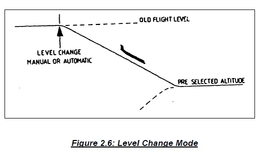
LEVEL CHANGE MODE
In the level change mode the AFCS makes steering signals to control the speed of the aircraft with the elevator. The AFCS stays in the level change mode until the aircraft is at the preselected altitude and then it goes to altitude hold.
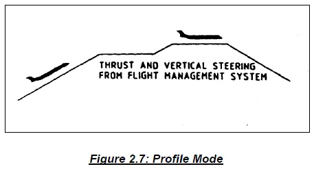
PROFILE MODE
In the profile mode the Flight Management System (FMS) gives vertical steering and thrust commands to the flight control computers. The FMS does all the altitude changes, altitude captures and altitude holds when the AFCS is in the profile mode.
HORIZONTAL MODES
There are the following horizontal modes:
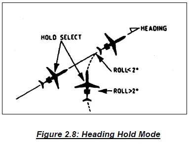
Heading hold mode: In the heading hold mode the AFCS makes steering signals to hold the aircrafts existing heading. When the AFCS comes in the HDG hold mode when the aircraft is in a roll, the AFCS first makes signals to level the aircraft off. The system holds the heading the aircraft has when the roll angle is two degrees or less.
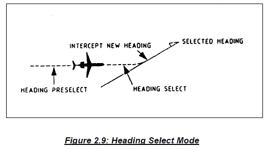
Heading select mode: In the heading select mode the AFCS makes steering signals to steer the aircraft to capture and hold a heading the crew selects on the flight mode panel. The flight mode panel also has a display to show the selected heading.
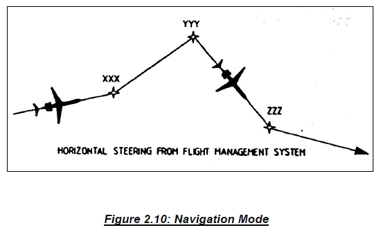
NAVIGATION MODE
In the navigation mode the flight management computer gives steering signals to the flight control computers to control the heading of the aircraft.
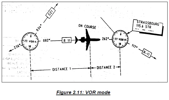
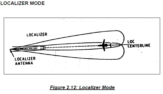
VOR MODE
In the VOR or localizer mode the flight control computers use VOR or LOC signals to make roll steering signals. On the EFIS control panel the cre selects the VOR or 1ocalizer receivers as input sensors.