FLIGHT INSTRUMENTS
Introduction
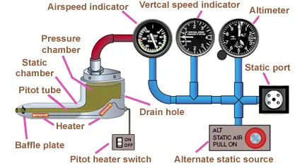
The instruments used in controlling the aircraft’s flight attitude are known as the flight instruments. There are basic flight instruments, such as the altimeter that displays aircraft altitude; the airspeed indicator; and the magnetic direction indicator, a form of compass. Additionally, an artificial horizon, turn coordinator, and vertical speed indicator are flight instruments present in most aircraft. This basic T arrangement for flight instruments is shown below.
A typical pitot-static system head, or pitot tube, collects ram air and static pressure for use by the flight instruments.
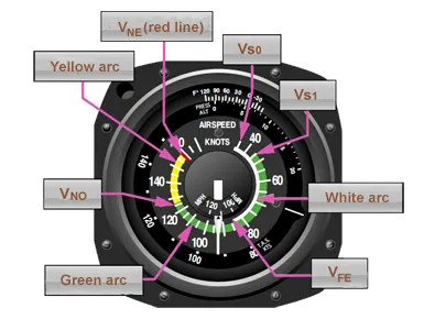
Airspeed Indicator (ASI)
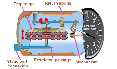
The VSI is a differential pressure gauge that compares free-flowing static air pressure in the diaphragm with restricted static air pressure around the diaphragm in the instrument case.

Airspeed indicator on single and light twin-engine aircraft with the standard color-coded markings.
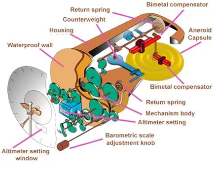
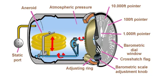
Altimeter
A sensitive altimeter is an aneroid barometer that measures the absolute pressure of the ambient air and displays it in terms of feet or meters above a selected pressure level.
Altimeter Jeager.
Vertical Speed Indicator (VSI)
Vertical Speed Indicator (VSI) is also called a vertical velocity indicator (VVI), and was formerly known as a rate-of-climb indicator. It is a rate-of-pressure change instrument that gives an indication of any deviation from a constant pressure level.
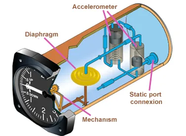
Instantaneous Vertical Speed Indicator.
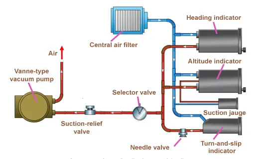
Pneumatic Systems
Pneumatic gyros are driven by a jet of air impinging on buckets cut into the periphery of the wheel. On many aircraft this stream of air is obtained by evacuating the instrument case with a vacuum source and allowing filtered air to flow into the case through a nozzle to spin the wheel.
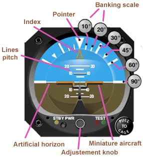
Attitude indicator
The attitude indicator, with its miniature aircraft and horizon bar, displays a picture of the attitude of the aircraft. The relationship of the miniature aircraft to the horizon bar is the same as the relationship of the real aircraft to the actual horizon. The instrument gives an instantaneous indication of even the smallest changes in attitude.
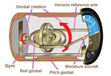
Presentation of the attitude indicator.
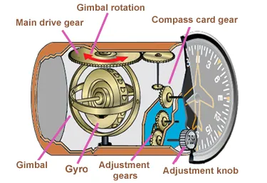
Heading indicator
The heading indicator is fundamentally a mechanical instrument designed to facilitate the use of the magnetic compass. Errors in the magnetic compass are numerous, making straight flight and precision turns to headings difficult to accomplish, particularly in turbulent air. A heading indicator displays headings based on a 360° azimuth, with the final zero omitted.
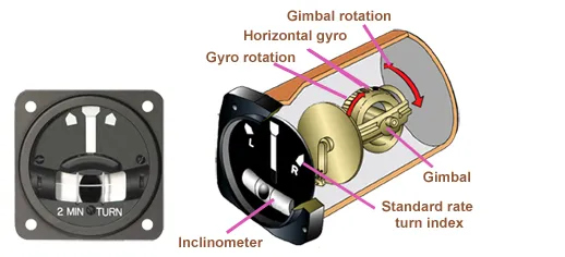
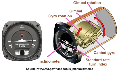
Turn-and-Slip Indicator
The first gyroscopic aircraft instrument was the turn indicator in the needle and ball, or turn-and-bank indicator, which has more recently been called a turn-and-slip indicator. The inclinometer in the instrument is a black glass ball sealed inside a curved glass tube that is partially filled with a liquid for damping. This ball measures the relative strength of the force of gravity and the force of inertia caused by a turn.
Turn and slip indicator.
Turn coordinator.
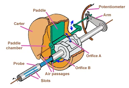
AOA sensors
There are two main types of AOA sensors in common use. Both detect the angular difference between the relative wind and the fuselage, which is used as a reference plane. One uses a vane, known as an alpha vane, externally mounted to the outside of the fuselage. It is free to rotate in the wind. As the AOA changes, air flowing over the vane changes its angle. The other (figure below) uses two slots in a probe that extends out of the side of the fuselage into the airflow.