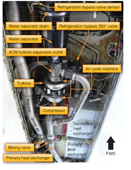
Figure 1. Boeing 737 air cycle system. The photo is taken looking up into the air conditioning bay located in the lower fuselage on each side of the aircraft
Aircraft Air Conditioning Systems
There are two types of air conditioning systems commonly used on aircraft. Air cycle air conditioning is used on most turbine-powered aircraft. It makes use of engine bleed air or APU pneumatic air during the conditioning process. Vapor cycle air conditioning systems are often used on reciprocating aircraft. This type system is similar to that found in homes and automobiles. Note that some turbine-powered aircraft also use vapor cycle air conditioning.
Air Cycle Air Conditioning
Air cycle air conditioning prepares engine bleed air to pressurize the aircraft cabin. The temperature and quantity of the air must be controlled to maintain a comfortable cabin environment at all altitudes and on the ground. The air cycle system is often called the air conditioning package or pack. It is usually located in the lower half of the fuselage or in the tail section of turbine-powered aircraft. [Figure 1]
|
Figure 1. Boeing 737 air cycle system. The photo is taken looking up into the air conditioning bay located in the lower fuselage on each side of the aircraft |
Air Cycle Air Conditioning System Operation
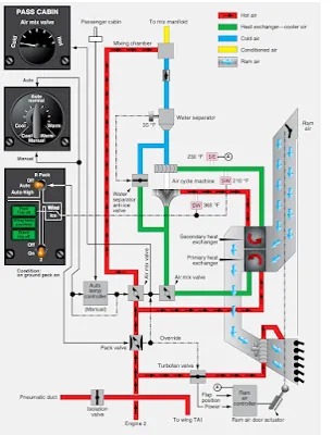
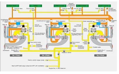
Even with the frigid temperatures experienced at high altitudes, bleed air is too hot to be used in the cabin without being cooled. It is let into the air cycle system and routed through a heat exchanger where ram air cools the bleed air. This cooled bleed air is directed into an air cycle machine. There, it is compressed before flowing through a secondary heat exchange that cools the air again with ram air. The bleed air then flows back into the air cycle machine where it drives an expansion turbine and cools even further. Water is then removed and the air is mixed with bypassed bleed air for final temperature adjustment. It is sent to the cabin through the air distribution system. By examining the operation of each component in the air cycle process, a better understanding can be developed of how bleed air is conditioned for cabin use. Refer to Figure 2, which diagrams the air cycle air conditioning system of the Boeing 737.
|
Figure 2. The air cycle air conditioning system on a Boeing 737 |
Pneumatic System Supply
The air cycle air conditioning system is supplied with air by the aircraft pneumatic system. In turn, the pneumatic system is supplied by bleed air tap-offs on each engine compressor section or from the APU pneumatic supply. An external pneumatic air supply source may also be connected while the aircraft is stationary on the ground. In normal flight operations, a pneumatic manifold is supplied by the engine bleed air through the use of valves, regulators, and ducting. The air conditioning packs are supplied by this manifold as are other critical airframe systems, such as the anti-ice and hydraulic pressurization system.
Air Cycle Air Conditioning System Component Operation
Pack Valve
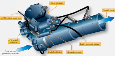
The pack valve is the valve that regulates bleed air from the pneumatic manifold into the air cycle air conditioning system. It is controlled with a switch from the air conditioning panel in the cockpit. Many pack valves are electrically controlled and pneumatically operated. Also known as the supply shutoff valve, the pack valve opens, closes, and modulates to allow the air cycle air conditioning system to be supplied with a designed volume of hot, pressurized air. [Figure 3] When an overheat or other abnormal condition requires that the air conditioning package be shut down, a signal is sent to the pack valve to close.
|
Figure 3. This pack valve drawing illustrates the complexity of the valve, which opens, closes, and modulates. It is manually actuated from the cockpit and automatically responds to supply and air cycle system parameter inputs |
Bleed Air Bypass
A means for bypassing some of the pneumatic air supplied to the air cycle air conditioning system around the system is present on all aircraft. This warm bypassed air must be mixed with the cold air produced by the air cycle system so the air delivered to the cabin is a comfortable temperature. It simultaneously controls the flow of bypassed air and air to be cooled to meet the requirements of the auto temperature controller. It can also be controlled manually with the cabin temperature selector in manual mode. Other air cycle systems may refer to the valve that controls the air bypassed around the air cycle cooling system as a temperature control valve, trim air pressure regulating valve, or something similar.
Primary Heat Exchanger
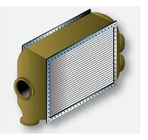
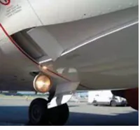
Generally, the warm air dedicated to pass through the air cycle system first passes through a primary heat exchanger. It acts similarly to the radiator in an automobile. A controlled flow of ram air is ducted over and through the exchanger, which reduces the temperature of the air inside the system. [Figure 4] A fan draws air through the ram air duct when the aircraft is on the ground so that the heat exchange is possible when the aircraft is stationary. In flight, ram air doors are modulated to increase or decrease ram air flow to the exchanger according to the position of the wing flaps. During slow flight, when the flaps are extended, the doors are open. At higher speeds, with the flaps retracted, the doors move toward the closed position reducing the amount of ram air to the exchanger. Similar operation is accomplished with a valve on smaller aircraft. [Figure 5]
|
Figure 4. The primary and secondary heat exchangers in an air cycle air conditioning system are of similar construction. They both cool bleed air when ram air passes over the exchanger coils and fins |
|
Figure 5. A ram air door controls the flow of air through the primary and secondary heat exchangers |
Refrigeration Turbine Unit or Air Cycle Machine and Secondary Heat Exchanger
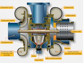
The heart of the air cycle air conditioning system is the refrigeration turbine unit, also known as the air cycle machine (ACM). It is comprised of a compressor that is driven by a turbine on a common shaft. System air flows from the primary heat exchanger into the compressor side of the ACM. As the air is compressed, its temperature rises. It is then sent to a secondary heat exchanger, similar to the primary heat exchanger located in the ram air duct. The elevated temperature of the ACM compressed air facilitates an easy exchange of heat energy to the ram air. The cooled system air, still under pressure from the continuous system air flow and the ACM compressor, exits the secondary heat exchanger. It is directed into the turbine side of the ACM. The steep blade pitch angle of the ACM turbine extracts more energy from the air as it passes through and drives the turbine. Once through, the air is allowed to expand at the ACM outlet, cooling even further. The combined energy loss from the air first driving the turbine and then expanding at the turbine outlet lowers the system air temperature to near freezing. [Figure 6]
|
Figure 6. A cutaway diagram of an air cycle machine. The main housing supports the single shaft to which the compressor and turbine are attached. Oil lubricates and cools the shaft bearings |
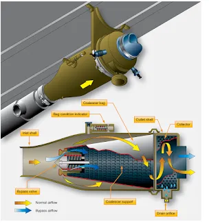
Water Separator
The cool air from the air cycle machine can no longer hold the quantity of water it could when it was warm. A water separator is used to remove the water from the saturated air before it is sent to the aircraft cabin. The separator operates with no moving parts. Foggy air from the ACM enters and is forced through a fiberglass sock that condenses and coalesces the mist into larger water drops. The convoluted interior structure of the separator swirls the air and water. The water collects on the sides of the separator and drains down and out of the unit, while the dry air passes through. A bypass valve is incorporated in case of a blockage. [Figure 7]
|
Figure 7. A water separator coalesces and removes water by swirling the air/water mixture from ACM expansion turbine. Centrifugal force sends the water to the walls of the collector where it drains from the unit |
Refrigeration Bypass Valve
As mentioned, air exiting the ACM turbine expands and cools. It becomes so cold, it could freeze the water in the water separator, thus inhibiting or blocking airflow. A temperature sensor in the separator controls a refrigeration bypass valve designed to keep the air flowing through the water separator above freezing temperature. The valve is also identified by other names such as a temperature control valve, 35° valve, anti-ice valve, and similar. It bypasses warm air around the ACM when opened. The air is introduced into the expansion ducting, just upstream of the water separator, where it heats the air just enough to keep it from freezing. Thus, the refrigeration bypass valve regulates the temperature of the ACM discharge air so it does not freeze when passing through the water separator. This valve is visible in Figure 1 and is diagrammed in the system in Figure 2.
All air cycle air conditioning systems use at least one ram air heat exchanger and an air cycle machine with expansion turbine to remove heat energy from the bleed air, but variations exist. An example of a system different from that described above is found on the McDonnell Douglas DC-10. Bleed air from the pneumatic manifold is compressed by the air cycle machine compressor before it flows to a single heat exchanger. Condensed water from the water separator is sprayed into the ram air at its entrance to the exchanger to draw additional heat from the compressed bleed air as the water evaporates. A trim air valve for each cabin zone mixes bypassed bleed air with conditioned air in response to individual temperature selectors for each zone. When cooling air demands are low, a turbine bypass valve routes some heat exchanger air directly to the conditioned air manifold. [Figure 8].
|
Figure 8. The air cycle air conditioning system of a DC-10 transport category aircraft uses only one heat exchanger per ACM |
Cabin Temperature Control System
Typical System Operation
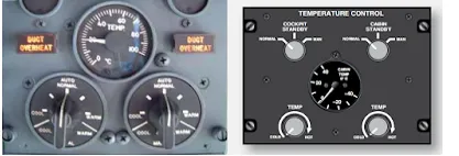
Most cabin temperature control systems operate in a similar manner. Temperature is monitored in the cabin, cockpit, conditioned air ducts, and distribution air ducts. These values are input into a temperature controller, or temperature control regulator, normally located in the electronics bay. A temperature selector in the cockpit can be adjusted to input the desired temperature. [Figure 9] The temperature controller compares the actual temperature signals received from the various sensors with the desired temperature input. Circuit logic for the selected mode processes these input signals. An output signal is sent to a valve in the air cycle air conditioning system. This valve has different names depending on the aircraft manufacturer and design of the environmental control systems (i.e., mixing valve, temperature control valve, trim air valve). It mixes warm bleed air that bypassed the air cycle cooling process with the cold air produced by it. By modulating the valve in response to the signal from the temperature controller, air of the selected temperature is sent to the cabin through the air distribution system.
|
Figure 9. Typical temperature selectors on a transport category aircraft temperature control panel in the cockpit (left) and a business jet (right). On large aircraft, temperature selectors may be located on control panels located in a particular cabin air distribution zone |