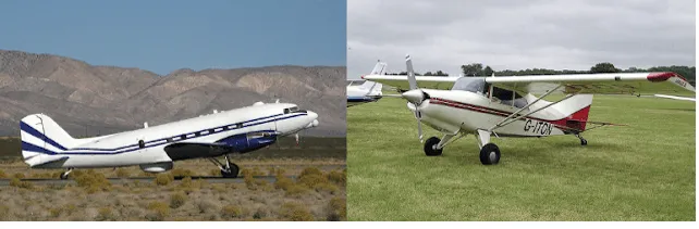
Figure 1. Tail wheel configuration landing gear on a DC-3 (left) and a STOL Maule MX-7-235 Super Rocket
Landing Gear Types and Arrangement
Landing Gear Arrangement
Three basic arrangements of landing gear are used: tail wheel-type landing gear (also known as conventional gear), tandem landing gear, and tricycle-type landing gear.
Tail Wheel Type Landing Gear
Tail wheel-type landing gear is also known as conventional gear because many early aircraft use this type of arrangement. The main gear are located forward of the center of gravity, causing the tail to require support from a third wheel assembly. A few early aircraft designs use a skid rather than a tail wheel. This helps slow the aircraft upon landing and provides directional stability. The resulting angle of the aircraft fuselage, when fitted with conventional gear, allows the use of a long propeller that compensates for older, underpowered engine design. The increased clearance of the forward fuselage offered by tail wheel-type landing gear is also advantageous when operating in and out of non-paved runways. Today, aircraft are manufactured with conventional gear for this reason and for the weight savings accompanying the relatively light tail wheel assembly. [Figure 1]
|
Figure 1. Tail wheel configuration landing gear on a DC-3 (left) and a STOL Maule MX-7-235 Super Rocket |
The proliferation of hard surface runways has rendered the tail skid obsolete in favor of the tail wheel. Directional control is maintained through differential braking until the speed of the aircraft enables control with the rudder. A steerable tail wheel, connected by cables to the rudder or rudder pedals, is also a common design. Springs are incorporated for dampening. [Figure 2]
|
Figure 2. The steerable tail wheel of a Pitts Special |
Tandem Landing Gear
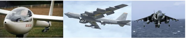
Few aircraft are designed with tandem landing gear. As the name implies, this type of landing gear has the main gear and tail gear aligned on the longitudinal axis of the aircraft. Sailplanes commonly use tandem gear, although many only have one actual gear forward on the fuselage with a skid under the tail. A few military bombers, such as the B-47 and the B-52, have tandem gear, as does the U2 spy plane. The VTOL Harrier has tandem gear but uses small outrigger gear under the wings for support. Generally, placing the gear only under the fuselage facilitates the use of very flexible wings. [Figure 3]
|
Figure 3. Tandem landing gear along the longitudinal axis of the aircraft permits the use of flexible wings on sailplanes (left) and select military aircraft like the B-52 (center). The VTOL Harrier (right) has tandem gear with outrigger-type gear |
Tricycle Type Landing Gear
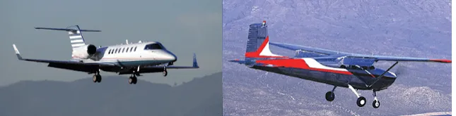
The most commonly used landing gear arrangement is the tricycle-type landing gear. It is comprised of main gear and nose gear. [Figure 4]
|
Figure 4. Tricycle-type landing gear with dual main wheels on a Learjet (left) and a Cessna 172, also with tricycle gear (right) |
Tricycle-type landing gear is used on large and small aircraft with the following benefits:
1. Allows more forceful application of the brakes without nosing over when braking, which enables higher landing speeds.
2. Provides better visibility from the flight deck, especially during landing and ground maneuvering.
3. Prevents ground-looping of the aircraft. Since the aircraft center of gravity is forward of the main gear, forces acting on the center of gravity tend to keep the aircraft moving forward rather than looping, such as with a tail wheel-type landing gear.
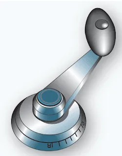
The nose gear of a few aircraft with tricycle-type landing gear is not controllable. It simply casters as steering is accomplished with differential braking during taxi. However, nearly all aircraft have steerable nose gear. On light aircraft, the nose gear is directed through mechanical linkage to the rudder pedals. Heavy aircraft typically utilize hydraulic power to steer the nose gear. Control is achieved through an independent tiller in the flight deck. [Figure 5]
|
Figure 5. A nose wheel steering tiller located on the flight deck |
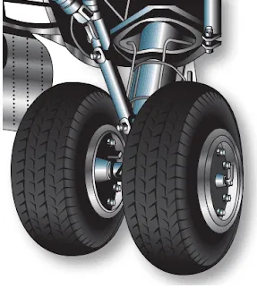
The main gear on a tricycle-type landing gear arrangement is attached to reinforced wing structure or fuselage structure. The number and location of wheels on the main gear vary. Many main gear have two or more wheels. [Figure 6]
|
Figure 6. Dual main gear of a tricycle-type landing gear |
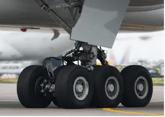
Multiple wheels spread the weight of the aircraft over a larger area. They also provide a safety margin should one tire fail. Heavy aircraft may use four or more wheel assemblies on each main gear. When more than two wheels are attached to a landing gear strut, the attaching mechanism is known as a bogie. The number of wheels included in the bogie is a function of the gross design weight of the aircraft and the surface type on which the loaded aircraft is required to land. Figure 7 illustrates the triple bogie main gear of a Boeing 777.
|
Figure 7. Triple bogie main landing gear assembly on a Boeing 777 |
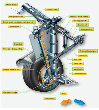
The tricycle-type landing gear arrangement consists of many parts and assemblies. These include air/oil shock struts, gear alignment units, support units, retraction and safety devices, steering systems, wheel and brake assemblies, etc. A main landing gear of a transport category aircraft is illustrated in Figure 8 with many of the parts identified as an introduction to landing gear nomenclature.
|
Figure 8. Nomenclature of a main landing gear bogie truck |
Fixed and Retractable Landing Gear
Further classification of aircraft landing gear can be made into two categories: fixed and retractable. Many small, single-engine light aircraft have fixed landing gear, as do a few light twins. This means the gear is attached to the airframe and remains exposed to the slipstream as the aircraft is flown. As the speed of an aircraft increases, so does parasite drag. Mechanisms to retract and stow the landing gear to eliminate parasite drag add weight to the aircraft. On slow aircraft, the penalty of this added weight is not overcome by the reduction of drag, so fixed gear is used. As the speed of the aircraft increases, the drag caused by the landing gear becomes greater and a means to retract the gear to eliminate parasite drag is required, despite the weight of the mechanism.
A great deal of the parasite drag caused by light aircraft landing gear can be reduced by building gear as aerodynamically as possible and by adding fairings or wheel pants to streamline the airflow past the protruding assemblies. A small, smooth profile to the oncoming wind greatly reduces landing gear parasite drag. Figure 9 illustrates a Cessna aircraft landing gear used on many of the manufacturer’s light planes. The thin cross section of the spring steel struts combine with the fairings over the wheel and brake assemblies to raise performance of the fixed landing gear by keeping parasite drag to a minimum.
|
Figure 9. Wheel fairings, or pants, and low profile struts reduce parasite drag on fixed gear aircraft |
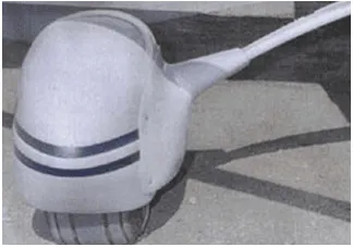
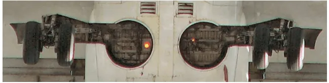
Retractable landing gear stow in fuselage or wing compartments while in flight. Once in these wheel wells, gear are out of the slipstream and do not cause parasite drag. Most retractable gear have a close fitting panel attached to them that fairs with the aircraft skin when the gear is fully retracted. [Figure 10] Other aircraft have separate doors that open, allowing the gear to enter or leave, and then close again.
|
Figure 10. The retractable gear of a Boeing 737 fair into recesses in the fuselage. Panels attached to the landing gear provide smooth airflow over the struts. The wheel assemblies mate with seals to provide aerodynamic flow without doors |