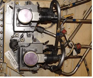
Figure 24. Emergency brake hydraulic fluid accumulators are precharged with nitrogen to deliver brake fluid to the brakes in the event normal and alternate hydraulic sources fail
Emergency Brake Systems
As can be seen in Figure 22, the brake metering valves not only receive hydraulic pressure from two separate hydraulic systems, they also feed two separate brake assemblies. Each main wheel assembly has two wheels. The inboard wheel brake and the outboard wheel brake, located in their respective wheel rims, are independent from each other. In case of hydraulic system failure or brake failure, each is independently supplied to adequately slow and stop the aircraft without the other. More complicated aircraft may involve another hydraulic system for back-up or use a similar alternation of sources and brake assemblies to maintain braking in case of hydraulic system or brake failure.
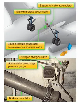
In addition to supply system redundancy, the brake accumulator is also an emergency source of power for the brakes in many power brake systems. The accumulator is pre-charged with air or nitrogen on one side of its internal diaphragm. Enough hydraulic fluid is contained on the other side of the diaphragm to operate the brakes in case of an emergency. It is forced out of the accumulator into the brakes through the system lines under enough stored pressure to slow the aircraft. Typically, the accumulator is located upstream of the brake control/metering valve to capitalize on the control given by the valve. [Figure 24]
|
Figure 24. Emergency brake hydraulic fluid accumulators are precharged with nitrogen to deliver brake fluid to the brakes in the event normal and alternate hydraulic sources fail |
Some simpler power brake systems may use an emergency source of brake power that is delivered directly to the brake assemblies and bypasses the remainder of the brake system completely. A shuttle valve immediately upstream of the brake units shifts to accept this source when pressure is lost from the primary supply sources. Compressed air or nitrogen is sometimes used. A pre-charged fluid source can also be used as an alternate hydraulic source.
Parking Brake
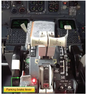
The parking brake system function is a combined operation. The brakes are applied with the rudder pedals and a ratcheting system holds them in place when the parking brake lever on the flight deck is pulled. [Figure 25] At the same time, a shut-off valve is closed in the common return line from the brakes to the hydraulic system. This traps the fluid in the brakes holding the rotors stationary. Depressing the pedals further releases the pedal ratchet and opens the return line valve.
|
Figure 25. The parking brake lever on a Boeing 737 center pedestal throttle quadrant |
Brake Deboosters
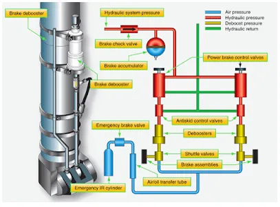
Some aircraft brake assemblies that operate on aircraft hydraulic system pressure are not designed for such high pressure. They provide effective braking through a power brake system but require less than maximum hydraulic system pressure. To supply the lower pressure, a brake debooster cylinder is installed downstream of the control valve and anti-skid valve. [Figure 26] The debooster reduces all pressure from the control valve to within the working range of the brake assembly.
|
Figure 26. The location of a brake debooster cylinder on a landing gear strut and the debooster’s position in relation to other components of a power brake system |
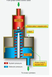
Brake deboosters are simple devices that use the application of force over different sized pistons to reduce pressure. [Figure 27] Their operation can be understood through the application of the following equation:
Pressure = Force/Area
High-pressure hydraulic system input pressure acts on the small end of a piston. This develops a force proportional to the area of the piston head. The other end of the piston is larger and housed in a separate cylinder. The force from the smaller piston head is transferred to the larger area of the other end of the piston. The amount of pressure conveyed by the larger end of the piston is reduced due to the greater area over which the force is spread. The volume of output fluid increases since a larger piston and cylinder are used. The reduced pressure is delivered to the brake assembly.
|
Figure 27. Brake deboosters |
The spring in the debooster aids in returning the piston to the ready position. If fluid is lost downstream of the deboost cylinder, the piston travels further down into the cylinder when the brakes are applied. The pin unseats the ball and allows fluid into the lower cylinder to replace what was lost. Once replenished, the piston rises up in the cylinder due to pressure build-up. The ball reseats as the piston travels above the pin and normal braking resumes. This function is not meant to permit leaks in the brake assemblies. Any leak discovered must be repaired by the technician. A lockout debooster functions as a debooster and a hydraulic fuse. If fluid is not encountered as the piston moves down in the cylinder, the flow of fluid to the brakes is stopped. This prevents the loss of all system hydraulic fluid should a rupture downstream of the debooster occur. Lockout deboosters have a handle to reset the device after it closes as a fuse. If not reset, no braking action is possible.
Anti-Skid
Large aircraft with power brakes require anti-skid systems. It is not possible to immediately ascertain in the flight deck when a wheel stops rotating and begins to skid, especially in aircraft with multiple-wheel main landing gear assemblies. A skid not corrected can quickly lead to a tire blowout, possible damage to the aircraft, and control of the aircraft may be lost.
System Operation
The anti-skid system not only detects wheel skid, it also detects when wheel skid is imminent. It automatically relieves pressure to the brake pistons of the wheel in question by momentarily connecting the pressurized brake fluid area to the hydraulic system return line. This allows the wheel to rotate and avoid a skid. Lower pressure is then maintained to the brake at a level that slows the wheel without causing it to skid.
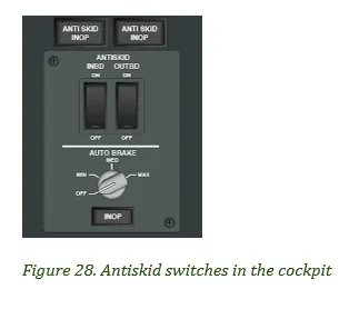
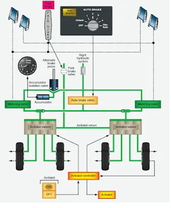
Maximum braking efficiency exists when the wheels are decelerating at a maximum rate but are not skidding. If a wheel decelerates too fast, it is an indication that the brakes are about to lock and cause a skid. To ensure that this does not happen, each wheel is monitored for a deceleration rate faster than a preset rate. When excessive deceleration is detected, hydraulic pressure is reduced to the brake on that wheel. To operate the anti-skid system, flight deck switches must be placed in the ON position. [Figure 28] After the aircraft touches down, the pilot applies and holds full pressure to the rudder brake pedals. The anti-skid system then functions automatically until the speed of the aircraft has dropped to approximately 20 mph. The system returns to manual braking mode for slow taxi and ground maneuvering.
|
|
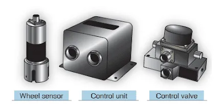
There are various designs of anti-skid systems. Most contain three main types of components: wheel speed sensors, anti-skid control valves, and a control unit. These units work together without human interference. Some anti-skid systems provide complete automatic braking. The pilot needs only to turn on the auto brake system, and the anti-skid components slow the aircraft without pedal input. [Figure 28] Ground safety switches are wired into the circuitry for anti-skid and auto brake systems. Wheel speed sensors are located on each wheel equipped with a brake assembly. Each brake also has its own anti-skid control valve. Typically, a single control box contains the anti-skid comparative circuitry for all of the brakes on the aircraft. [Figure 29]
|
Figure 29. A wheel sensor (left), a control unit (center), and a control valve (right) are components of an antiskid system. A sensor is located on each wheel equipped with a brake assembly. An antiskid control valve for each brake assembly is controlled from a single central control unit |
Wheel Speed Sensors
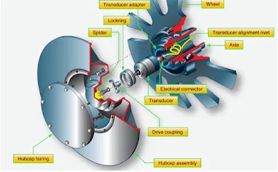
Wheel speed sensors are transducers. They may be alternating current (AC) or direct current (DC). The typical AC wheel speed sensor has a stator mounted in the wheel axle. A coil around it is connected to a controlled DC source so that when energized, the stator becomes an electromagnet. A rotor that turns inside the stator is connected to the rotating wheel hub assembly through a drive coupling so that it rotates at the speed of the wheel. Lobes on the rotor and stator cause the distance between the two components to constantly change during rotation. This alters the magnetic coupling or reluctance between the rotor and stator. As the electromagnetic field changes, a variable frequency AC is induced in the stator coil. he frequency is directly proportional to the speed of rotation of the wheel. The AC signal is fed to the control unit for processing. A DC wheel speed sensor is similar, except that a DC is produced the magnitude of which is directly proportional to wheel speed. [Figure 30]
|
Figure 30. The stator of an antiskid wheel sensor is mounted in the axle, and the rotor is coupled to the wheel hub spider that rotates with the wheel |
Control Units
The control unit can be regarded as the brain of the anti-skid system. It receives signals from each of the wheel sensors. Comparative circuits are used to determine if any of the signals indicate a skid is imminent or occurring on a particular wheel. If so, a signal is sent to the control valve of the wheel to relieve hydraulic pressure to that brake which prevents or relieves the skid. The control unit may or may not have external test switches and status indicating lights. It is common for it to be located in the avionics bay of the aircraft. [Figure 31]
|
Figure 31. A rack mounted antiskid control unit from an airliner |
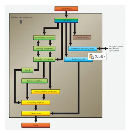
The Boeing anti-skid control valve block diagram in Figure 32 gives further detail on the functions of an anti-skid control unit. Other aircraft may have different logic to achieve similar end results. DC systems do not require an input converter since DC is received from the wheel sensors, and the control unit circuitry operates primarily with DC. Only the functions on one circuit card for one wheel brake assembly are shown in Figure 32. Each wheel has its own identical circuitry card to facilitate simultaneous operation. All cards are housed in a single control unit that Boeing calls a control shield.
|
Figure 32. A Boeing 737 antiskid control unit internal block diagram |
The converter shown changes the AC frequency received from the wheel sensor into DC voltage that is proportional to wheel speed. The output is used in a velocity reference loop that contains deceleration and velocity reference circuits. The converter also supplies input for the spoiler system and the locked wheel system, which is discussed at the end of this section. A velocity reference loop output voltage is produced, which represents the instantaneous velocity of the aircraft. This is compared to converter output in the velocity comparator. This comparison of voltages is essentially the comparison of the aircraft speed to wheel speed. The output from the velocity comparator is a positive or negative error voltage corresponding to whether the wheel speed is too fast or too slow for optimum braking efficiency for a given aircraft speed.
The error output voltage from the comparator feeds the pressure bias modulator circuit. This is a memory circuit that establishes a threshold where the pressure to the brakes provides optimum braking. The error voltage causes the modulator to either increase or decrease the pressure to the brakes in attempt to hold the modulator threshold. It produces a voltage output that is sent to the summing amplifier to do this. A lead output from the comparator anticipates when the tire is about to skid with a voltage that decreases the pressure to the brake. It sends this voltage to the summing amplifier as well. A transient control output from the comparator designed for rapid pressure dump when a sudden skid has occurred also sends voltage to the summing amp. As the name suggests, the input voltages to the amplifier are summed, and a composite voltage is sent to the valve driver. The driver prepares the current required to be sent to the control valve to adjust the position of the valve. Brake pressure increases, decreases, or holds steady depending on this value.
Anti-Skid Control Valves
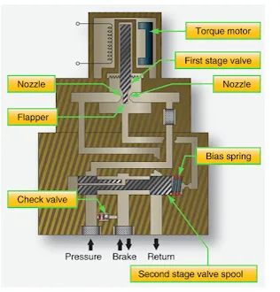
Anti-skid control valves are fast-acting, electrically controlled hydraulic valves that respond to the input from the anti-skid control unit. There is one control valve for each brake assembly. A torque motor uses the input from the valve driver to adjust the position of a flapper between two nozzles. By moving the flapper closer to one nozzle or the other, pressures are developed in the second stage of the valve. These pressures act on a spool that is positioned to build or reduce pressure to the brake by opening and blocking fluid ports. [Figure 33]
|
Figure 33. An antiskid control valve uses a torque motor controlled flapper in the first stage of the valve to adjust pressure on a spool in the second stage of the valve to build or relieve pressure to the brake |
As pressure is adjusted to the brakes, deceleration slows to within the range that provides the most effective braking without skidding. The wheel sensor signal adjusts to the wheel speed, and the control unit processes the change. Output is altered to the control valve. The control valve flapper position is adjusted and steady braking resumes without correction until needed. Anti-skid control valves are typically located in the main wheel for close access to hydraulic pressure and return manifolds, as well as the brake assemblies. [Figure 34] Systematically, they are positioned downstream of the power brake control valves but upstream of debooster cylinders if the aircraft is so equipped as was shown in Figure 26.
|
Figure 34. Two antiskid control valves with associated plumbing and wiring |
Touchdown and Lock Wheel Protection
It is essential that the brakes are not applied when the aircraft contacts the runway upon landing. This could cause immediate tire blowout. A touchdown protection mode is built into most aircraft anti-skid systems to prevent this. It typically functions in conjunction with the wheel speed sensor and the air/ground safety switch on the landing gear strut (squat switch). Until the aircraft has weight on wheels, the detector circuitry signals the anti-skid control valve to open the passage between the brakes and the hydraulic system return, thus preventing pressure build-up and application of the brakes. Once the squat switch is open, the anti-skid control unit sends a signal to the control valve to close and permit brake pressure build-up. As a back-up and when the aircraft is on the ground with the strut not compressed enough to open the squat switch, a minimum wheel speed sensor signal can override and allow braking. Wheels are often grouped with one relying on the squat switch and the other on wheel speed sensor output to ensure braking when the aircraft is on the ground, but not before then.
Locked wheel protection recognizes if a wheel is not rotating. When this occurs, the anti-skid control valve is signaled to fully open. Some aircraft anti-skid control logic, such as the Boeing 737 shown in Figure 33, expands the locked wheel function. Comparator circuitry is used to relieve pressure when one wheel of a paired group of wheels rotates 25 percent slower than the other. Inboard and outboard pairs are used because if one of the pair is rotating at a certain speed, so should the other. If it is not, a skid is beginning or has occurred. On takeoff, the anti-skid system receives input through a switch located on the gear selector that shuts off the anti-skid system. This allows the brakes to be applied as retraction occurs so that no wheel rotation exists while the gear is stowed.
Auto Brakes
Aircraft equipped with auto brakes typically bypass the brake control valves or brake metering valves and use a separate auto brake control valve to provide this function. In addition to the redundancy provided, auto brakes rely on the anti-skid system to adjust pressure to the brakes if required due to an impending skid. Figure 35 shows a simplified diagram of the Boeing 757 brake system with the auto brake valve in relation to the main metering valve and anti-skid valves in this eight-main wheel system.
|
Figure 35. The Boeing 757 normal brake system with auto brake and antiskid |
Anti-Skid System Tests
It is important to know the status of the anti-skid system prior to attempting to use it during a landing or aborted takeoff. Ground tests and in-flight tests are used. Built-in test circuits and control features allow testing of the system components and provide warnings should a particular component or part of the system become inoperative. An inoperative anti-skid system can be shut off without affecting normal brake operation.
Ground Test
Ground tests vary slightly from aircraft to aircraft. Consult the manufacturer’s maintenance manual for test procedures specific to the aircraft in question. Much of the anti-skid system testing originates from testing circuits in the anti-skid control unit. Built-in test circuits continuously monitor the anti-skid system and provide warning if a failure occurs. An operational test can be performed before flight. The anti-skid control switch and/or test switch is used in conjunction with system indicator light(s) to determine system integrity. A test is first done with the aircraft at rest and then in an electrically simulated anti-skid braking condition. Some anti-skid control units contain system and component testing switches and lights for use by the technician. This accomplishes the same operational verification, but allows an additional degree of troubleshooting. Test sets are available for anti-skid systems that produce electric signals that simulate speed outputs of the wheel transducer, deceleration rates, and flight/ground parameters.
In -Flight Test
In-flight testing of the anti-skid system is desirable and part of the pre-landing checklist so that the pilot is aware of system capability before landing. As with ground testing, a combination of switch positions and indicator lights are used according to information in the aircraft operations manual.
Anti-Skid System Maintenance
Anti-skid components require little maintenance. Troubleshooting anti-skid system faults is either performed via test circuitry or can be accomplished through isolation of the fault to one of the three main operating components of the system. Anti-skid components are normally not repaired in the field. They are sent to the manufacturer or a certified repair station when work is required. Reports of anti-skid system malfunction are sometimes malfunctions of the brake system or brake assemblies. Ensure brake assemblies are bled and functioning normally without leaks before attempting to isolate problems in the anti-skid system.
Wheel Speed Sensor
Wheel speed sensors must be securely and correctly mounted in the axle. The means of keeping contamination out of the sensor, such as sealant or a hub cap, should be in place and in good condition. The wiring to the sensor is subject to harsh conditions and should be inspected for integrity and security. It should be repaired or replaced if damaged in accordance with the manufacturer’s instructions. Accessing the wheel speed sensor and spinning it by hand or other recommended device to ensure brakes apply and release via the anti-skid system is common practice.
Control Valve
Anti-skid control valve and hydraulic system filters should be cleaned or replaced at the prescribed intervals. Follow all manufacturer’s instructions when performing this maintenance. Wiring to the valve must be secure, and there should be no fluid leaks.
Control Unit
Control units should be securely mounted. Test switches and indicators, if any, should be in place and functioning. It is essential that wiring to the control unit is secure. A wide variety of control units are in use. Follow the manufacturer’s instructions at all times when inspecting or attempting to perform maintenance on these units.